SmartFit 3D
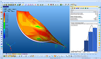
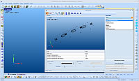
SmartFit® 3D is a fast, accurate and reliable 2D/3D best-fitting and analysis software package that compares CAD/nominal models to data from most measurement systems.
SmartFit 3D is an interactive software environment where measured data is analyzed, optimized and compared to CAD and theorethical data.
SmartFit 3D starts working where your measuring tools leave off. This powerful, intuitive software accepts measured data from virtually any contact or non-contact inspection device, including CMMs, laser scanners, laser trackers and video systems. Data are compared to the nominal representation of a part (CAD model, drawings, nominal points) to optimize their positions. Intelligent best-fitting mathematical methods provide thorough analysis, optimization, and evaluation of conformance to form and location for 2D/3D rigid bodies and assemblies.
Two Distinct Working Modes
Data imported into SmartFit 3D can be optimized in "Point to Point" or "Point to Surface" mode. In "Point to Point" mode the nominal coordinates of each measured points are explicitly defined, and remain unchanged during the entire optimization process. "Point to Surface" mode represents the nominal part with a CAD model, while the nominal points are represented by the projected coordinates, which usually vary at each optimization step.
An Intelligent Optimization Process
"How can a good part be machined from the casting?"
"Will all the points satisfy the tolerance?"
"How much of a certain components should be shifted or rotated to achieve correct assembly?"
SmartFit 3D works with you to answer questions like these that impact your bottom line. Using advanced best-fit algorithms, your part is precisely evaluated against the nominal model to solve misalignment and location problems so that it can be repositioned for machining. The extracting SmartFit 3D process uses eight mathematical criteria to get the job done.
What Problems Can It Solve with SmartFit 3D?
Use SmartFit 3D to make intelligent decisions:
- Best-fit a part to its tolerance zone
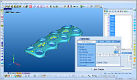
- Assess profile tolerances on complex surfaces
- Find the best coordinate system for machining
- Determine the best achievable tolerance
- Find set-up problems and determine new, better datum targets
- Troubleshoot the manufacturing process using intelligent "what if" analysis
- Analyze assembles and provide advice on correction
Key Features
Features
- Eight mathematical criteria for best-fitting – Least squares, Minimum Sum of Deviations, Mini-Max, Uniform Deviations, Minimum Standard Deviation, Tolerance Envelope and Tolerance Envelope Mini-Max
- Calculation with uncertainty information – best fitting can take measurements uncertainities into account if provided. Optimization algorithms will achieve the best solution, with all uncertainty zones put into tolerance
- Tools for forcing a solution by weighting, excluding or releasing points
- Calculation of basic geometric elements certified by PTB
- Cross-sectioning capability – allows creation of cross sections from high complexity freeform models, with analysis of errors in 2D
- Cross section can be included in reports or exported for further analysis
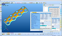
- Multiple error display modes, including color mapping, statistics, graphics snapshots and detailed point/error information
- "Point to Point" and "Point to Surface" working modes
- Built-in filters automatically invoked during measured data import
- Annotations and basic dimensioning capability
- Discrete reverse engineering, 2.5D and 3D mesh construction from point clouds
Import/Export Options
- Import measured points with or without probe tip radius
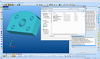
- Import CAD file – compatible with IGES,VDA, STL, DXF, STEP and SFM formats
- Import native CAD models (CATIA, Parasolid, Solidworks, ProE, ACIS, Ideas) via optional CAD converter
- Import measured point data with point filtering options, including Smart, Gaussian, Median, Morphology and Curvature-based point reduction
- Export to SmartFit/SmartProfile Model (SFM) format
- Export to STL format
- Export whiskers to an IGES file
- Export screen captures
- Export results to an Excel file
- Export mesh points of a model
- Export creoo section as a 2D SmartFit project
Capabilities
- Assess profile tolerances of complex surfaces, determining the best achie-vable tolerance
- Simulate corrections for assemblies
- Achieve maximum material conditions for machining
- System identification of new, better datum targets (locators)
- Determine best coordinate system for machining
- "What if" analysis during optimization
- Create simple models – without a CAD system
- Compare two or more model surfaces
- Construct mesh surfaces
- Evaluate measured data against a nominal model
- Evaluate more than one imported point cloud against a nominal model
- Evaluate measured data against more than one imported or constructed model
- Associate measured points with specific geometric features
- Automatically process data with AutoRun
What's New
Point filtering as part of the import process:
- QSP
- Skip points
- Gaussian point filter
- Morphology filters: Open then Close, Close then Open
- PAMS compensation
Support CoreTechnologie's CAD converter to import native (CATIA, ProEngineer, SolidWorks...) CAD formats
Download Brochure
SmartFit 3D Brochure
PDF (1.67 MB)
System Requirements
| Operating System | Microsoft®Windows™ 7 (32 or 64 bit), 8/8.1(32or 64 bit), or 10 (32 or 64 bit), 64 bit recommended for all OS |
| CPU | Intel®compatible 2GHz or better (Multi-core recommended) |
| Monitor |
Recommended: Full HD(1920x1080) or higher Required: HD(1280x720) |
| Memory |
32 bit: 4 GB 64 bit: 8GB minimum (16GB or more recommended) |
| Free Disk Space | 20 GB or more |
| GPU |
OpenGL 1.1 compliance is required nVidia graphics cards are recommended Onboardgraphics chipsets, Intel graphics cards, and standard VGA only graphics cards are not supported |


